Elementary Logic Gates
#1.2.1 The Nand Gate
| A | B | OUT |
|---|---|---|
| 0 | 0 | 1 |
| 0 | 1 | 1 |
| 1 | 0 | 1 |
| 1 | 1 | 0 |
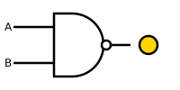
The starting point of our computer architecture is the Nand gate, from which all other gates and chips are built. The Nand gate is designed to compute the following Boolean function:
Throughout the book, we use “chip API boxes” to specify chips. For each chip, the API specifies the chip name, the names of its input and output pins, the function or operation that the chip effects, and an optional comment.
Inputs: a, b
Outputs: out
Function: If a=b=1 then out =0 else out =1
Comment: This gate is considered primitive and thus there is no need to implement it.
SPOILERS
This gate is primitive; no implementation needed.
#1.2.2 Basic Logic Gates
Some of the logic gates presented here are typically referred to as “elementary” or “basic.” At the same time, every one of them can be composed from Nand gates alone. Therefore, they need not be viewed as primitive.
#Not
| INPUT | OUTPUT |
|---|---|
| 0 | 1 |
| 1 | 0 |
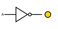
The single-input Not gate, also known as “converter,” converts its input from 0 to 1 and vice versa. The gate API is as follows:
Inputs: in
Outputs: out
Function: If in=0 then out =1 else out =0.
SPOILERS
One POSSIBLE implementation uses: Nand
#And
| A | B | OUTPUT |
|---|---|---|
| 0 | 0 | 0 |
| 0 | 1 | 0 |
| 1 | 0 | 0 |
| 1 | 1 | 1 |
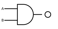
The And function returns 1 when both its inputs are 1, and 0 otherwise.
Inputs: a, b
Outputs: out
Function: If a=b=1 then out =1 else out =0.
SPOILERS
One POSSIBLE implementation uses: Nand, Not
#Or
| A | B | OUTPUT |
|---|---|---|
| 0 | 0 | 0 |
| 0 | 1 | 1 |
| 1 | 0 | 1 |
| 1 | 1 | 1 |
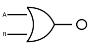
The Or function returns 1 when at least one of its inputs is 1, and 0 otherwise.
Inputs: a, b
Outputs: out
Function: If a=b=0 then out =0 else out =1.
SPOILERS
One POSSIBLE implementation uses: Nand
#Xor
| A | B | OUTPUT |
|---|---|---|
| 0 | 0 | 0 |
| 0 | 1 | 1 |
| 1 | 0 | 1 |
| 1 | 1 | 0 |
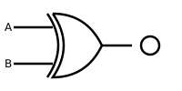
The Xor function, also known as “exclusive or,” returns 1 when its two inputs have opposing values, and 0 otherwise.
Inputs: a, b
Outputs: out
Function: If a ≠ b then out =1 else out =0.
SPOILERS
One POSSIBLE implementation uses: Not, And, Or
#Multiplexor
| A | B | SEL | OUT |
|---|---|---|---|
| 0 | 0 | 0 | 0 |
| 0 | 0 | 1 | 0 |
| 0 | 1 | 0 | 0 |
| 0 | 1 | 1 | 1 |
| 1 | 0 | 0 | 1 |
| 1 | 0 | 1 | 0 |
| 1 | 1 | 0 | 1 |
| 1 | 1 | 1 | 1 |
| SEL | OUT |
|---|---|
| 0 | a |
| 1 | b |
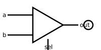
A multiplexor (figure 1.8) is a three-input gate that uses one of the inputs, called “selection bit,” to select and output one of the other two inputs, called “data bits.” Thus, a better name for this device might have been selector. The name multiplexor was adopted from communications systems, where similar devices are used to serialize (multiplex) several input signals over a single output wire.
Inputs: a, b, sel
Outputs: out
Function: If sel =0 then out =a else out =b.
SPOILERS
One POSSIBLE implementation uses: Not, And, Or
#DeMultiplexor
| IN | SEL | A | B |
|---|---|---|---|
| 0 | 0 | 0 | 0 |
| 0 | 1 | 0 | 0 |
| 1 | 0 | 1 | 0 |
| 1 | 1 | 0 | 1 |
| SEL | A | B |
|---|---|---|
| 0 | IN | 0 |
| 1 | 0 | IN |
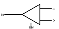
A demultiplexor (figure 1.9) performs the opposite function of a multiplexor: It takes a single input and channels it to one of two POSSIBLE outputs according to a selector bit that specifies which output to chose.
Inputs: in, sel
Outputs: a, b
Function: If sel=0 then {a=in, b=0} else {a=0, b=in}.
SPOILERS
One POSSIBLE implementation uses: Not, And
#1.2.3 Multi-Bit Versions of Basic Gates
Computer hardware is typically designed to operate on multi-bit arrays called “buses.” For example, a basic requirement of a 32-bit computer is to be able to compute (bit-wise) an And function on two given 32-bit buses. To implement this operation, we can build an array of 32 binary And gates, each operating separately on a pair of bits. In order to enclose all this logic in one package, we can encapsulate the gates array in a single chip interface consisting of two 32-bit input buses and one 32-bit output bus.
This section describes a typical set of such multi-bit logic gates, as needed for the construction of a typical 16-bit computer. We note in passing that the architecture of n-bit logic gates is basically the same irrespective of n’s value. When referring to individual bits in a bus, it is common to use an array syntax. For example, to refer to individual bits in a 16-bit bus named data, we use the notation data[0], data[1], data[15].
#Multi-Bit Not
An n-bit Not gate applies the Boolean operation Not to every one of the bits in its n-bit input bus:
Inputs: in[16] // a 16-bit pin
Outputs: out[16]
Function: For i=0..15 out[i]=Not(in[i]).
SPOILERS
One POSSIBLE implementation uses: Not
| in | out |
|---|---|
| 0000000000000000 | 1111111111111111 |
| 1111111111111111 | 0000000000000000 |
| 1010101010101010 | 0101010101010101 |
| 0011110011000011 | 1100001100111100 |
| 0001001000110100 | 1110110111001011 |
#Multi-Bit And
An n-bit And gate applies the Boolean operation And to every one of the n bit-pairs arrayed in its two n-bit input buses:
Inputs: a[16], b[16]
Outputs: out[16]
Function: For i=0..15 out[i]=And(a[i],b[i]).
SPOILERS
One POSSIBLE implementation uses: And
| a | b | out |
|---|---|---|
| 0000000000000000 | 0000000000000000 | 0000000000000000 |
| 0000000000000000 | 1111111111111111 | 0000000000000000 |
| 1111111111111111 | 1111111111111111 | 1111111111111111 |
| 1010101010101010 | 0101010101010101 | 0000000000000000 |
| 0011110011000011 | 0000111111110000 | 0000110011000000 |
| 0001001000110100 | 1001100001110110 | 0001000000110100 |
#Multi-Bit Or
An n-bit Or gate applies the Boolean operation Or to every one of the n bit-pairs arrayed in its two n-bit input buses:
Inputs: a[16], b[16]
Outputs: out[16]
Function: For i=0..15 out[i]=Or(a[i],b[i]).
SPOILERS
One POSSIBLE implementation uses: Or
| a | b | out |
|---|---|---|
| 0000000000000000 | 0000000000000000 | 0000000000000000 |
| 0000000000000000 | 1111111111111111 | 1111111111111111 |
| 1111111111111111 | 1111111111111111 | 1111111111111111 |
| 1010101010101010 | 0101010101010101 | 1111111111111111 |
| 0011110011000011 | 0000111111110000 | 0011111111110011 |
| 0001001000110100 | 1001100001110110 | 1001101001110110 |
#Multi-Bit Multiplexor
An n-bit multiplexor is exactly the same as the binary multiplexor described in figure 1.8, except that the two inputs are each n-bit wide; the selector is a single bit.
Inputs: a[16], b[16], sel
Outputs: out[16]
Function: If sel=0 then for i=0..15 out[i]=a[i]
else for i=0..15 out[i]=b[i].
SPOILERS
One POSSIBLE implementation uses: Mux
| a | b | sel | out |
|---|---|---|---|
| 0000000000000000 | 0000000000000000 | 0 | 0000000000000000 |
| 0000000000000000 | 0000000000000000 | 1 | 0000000000000000 |
| 0000000000000000 | 0001001000110100 | 0 | 0000000000000000 |
| 0000000000000000 | 0001001000110100 | 1 | 0001001000110100 |
| 1001100001110110 | 0000000000000000 | 0 | 1001100001110110 |
| 1001100001110110 | 0000000000000000 | 1 | 0000000000000000 |
| 1010101010101010 | 0101010101010101 | 0 | 1010101010101010 |
| 1010101010101010 | 0101010101010101 | 1 | 0101010101010101 |
#1.2.4 Multi-Way Versions of Basic Gates
Many 2-way logic gates that accept two inputs have natural generalization to multi-way variants that accept an arbitrary number of inputs. This section describes a set of multi-way gates that will be used subsequently in various chips in our computer architecture. Similar generalizations can be developed for other architectures, as needed.
#Multi-Way Or
An n-way Or gate outputs 1 when at least one of its n bit inputs is 1, and 0 otherwise. Here is the 8-way variant of this gate:
Inputs: in[8]
Outputs: out
Function: out=Or(in[0],in[1],...,in[7]).
SPOILERS
One POSSIBLE implementation uses: Or
| in | out |
|---|---|
| 00000000 | 0 |
| 11111111 | 1 |
| 00010000 | 1 |
| 00000001 | 1 |
| 00100110 | 1 |
#Multi-Way/Multi-Bit Multiplexor
An m-way n-bit multiplexor selects one of m n-bit input buses and outputs it to a single n-bit output bus. The selection is specified by a set of k control bits, where k=log_{2}m. Figure 1.10 depicts a typical example.
The computer platform that we develop in this book requires two variations of this chip: A 4-way 16-bit multiplexor and an 8-way 16-bit multiplexor:
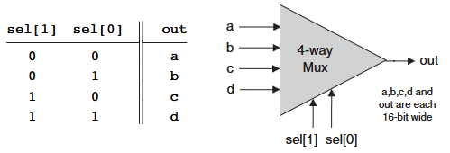
Inputs: a[16], b[16], c[16], d[16], sel[2]
Outputs: out[16]
Function: If sel=00 then out =a else if sel=01 then out =b else if sel=10 then out =c else if sel=11 then out =d
Comment: The assignment operations mentioned above are all 16-bit. For example, “out=a” means “for i=0..15 out[i]=a[i]”.
SPOILERS
One POSSIBLE implementation uses: Mux16
| a | b | c | d | sel | out |
|---|---|---|---|---|---|
| 0000000000000000 | 0000000000000000 | 0000000000000000 | 0000000000000000 | 00 | 0000000000000000 |
| 0000000000000000 | 0000000000000000 | 0000000000000000 | 0000000000000000 | 01 | 0000000000000000 |
| 0000000000000000 | 0000000000000000 | 0000000000000000 | 0000000000000000 | 10 | 0000000000000000 |
| 0000000000000000 | 0000000000000000 | 0000000000000000 | 0000000000000000 | 11 | 0000000000000000 |
| 0001001000110100 | 1001100001110110 | 1010101010101010 | 0101010101010101 | 00 | 0001001000110100 |
| 0001001000110100 | 1001100001110110 | 1010101010101010 | 0101010101010101 | 01 | 1001100001110110 |
| 0001001000110100 | 1001100001110110 | 1010101010101010 | 0101010101010101 | 10 | 1010101010101010 |
| 0001001000110100 | 1001100001110110 | 1010101010101010 | 0101010101010101 | 11 | 0101010101010101 |
Inputs: a[16], b[16], c[16], d[16], e[16], f[16], g[16], h[16], sel[3]
Outputs: out[16]
Function: If sel=000 then out =a else if sel=001 then out =b else if sel=010 out =c ... else if sel=111 then out =h
Comment: The assignment operations mentioned above are all 16-bit. For example, “out=a” means “for i=0..15 out[i]=a[i]”.
SPOILERS
One POSSIBLE implementation uses: Mux16
| a | b | c | d | e | f | g | h | sel | out |
|---|---|---|---|---|---|---|---|---|---|
| 0000000000000000 | 0000000000000000 | 0000000000000000 | 0000000000000000 | 0000000000000000 | 0000000000000000 | 0000000000000000 | 0000000000000000 | 000 | 0000000000000000 |
| 0000000000000000 | 0000000000000000 | 0000000000000000 | 0000000000000000 | 0000000000000000 | 0000000000000000 | 0000000000000000 | 0000000000000000 | 001 | 0000000000000000 |
| 0000000000000000 | 0000000000000000 | 0000000000000000 | 0000000000000000 | 0000000000000000 | 0000000000000000 | 0000000000000000 | 0000000000000000 | 010 | 0000000000000000 |
| 0000000000000000 | 0000000000000000 | 0000000000000000 | 0000000000000000 | 0000000000000000 | 0000000000000000 | 0000000000000000 | 0000000000000000 | 011 | 0000000000000000 |
| 0000000000000000 | 0000000000000000 | 0000000000000000 | 0000000000000000 | 0000000000000000 | 0000000000000000 | 0000000000000000 | 0000000000000000 | 100 | 0000000000000000 |
| 0000000000000000 | 0000000000000000 | 0000000000000000 | 0000000000000000 | 0000000000000000 | 0000000000000000 | 0000000000000000 | 0000000000000000 | 101 | 0000000000000000 |
| 0000000000000000 | 0000000000000000 | 0000000000000000 | 0000000000000000 | 0000000000000000 | 0000000000000000 | 0000000000000000 | 0000000000000000 | 110 | 0000000000000000 |
| 0000000000000000 | 0000000000000000 | 0000000000000000 | 0000000000000000 | 0000000000000000 | 0000000000000000 | 0000000000000000 | 0000000000000000 | 111 | 0000000000000000 |
| 0001001000110100 | 0010001101000101 | 0011010001010110 | 0100010101100111 | 0101011001111000 | 0110011110001001 | 0111100010011010 | 1000100110101011 | 000 | 0001001000110100 |
| 0001001000110100 | 0010001101000101 | 0011010001010110 | 0100010101100111 | 0101011001111000 | 0110011110001001 | 0111100010011010 | 1000100110101011 | 001 | 0010001101000101 |
| 0001001000110100 | 0010001101000101 | 0011010001010110 | 0100010101100111 | 0101011001111000 | 0110011110001001 | 0111100010011010 | 1000100110101011 | 010 | 0011010001010110 |
| 0001001000110100 | 0010001101000101 | 0011010001010110 | 0100010101100111 | 0101011001111000 | 0110011110001001 | 0111100010011010 | 1000100110101011 | 011 | 0100010101100111 |
| 0001001000110100 | 0010001101000101 | 0011010001010110 | 0100010101100111 | 0101011001111000 | 0110011110001001 | 0111100010011010 | 1000100110101011 | 100 | 0101011001111000 |
| 0001001000110100 | 0010001101000101 | 0011010001010110 | 0100010101100111 | 0101011001111000 | 0110011110001001 | 0111100010011010 | 1000100110101011 | 101 | 0110011110001001 |
| 0001001000110100 | 0010001101000101 | 0011010001010110 | 0100010101100111 | 0101011001111000 | 0110011110001001 | 0111100010011010 | 1000100110101011 | 110 | 0111100010011010 |
| 0001001000110100 | 0010001101000101 | 0011010001010110 | 0100010101100111 | 0101011001111000 | 0110011110001001 | 0111100010011010 | 1000100110101011 | 111 | 1000100110101011 |
#Multi-Way/Multi-Bit Demultiplexor
An m-way n-bit demultiplexor (figure 1.11) channels a single n-bit input into one of m possible n-bit outputs. The selection is specified by a set of k control bits, where k=log_{2}m.
The specific computer platform that we will build requires two variations of this chip: A 4-way 1-bit demultiplexor and an 8-way 1-bit multiplexor, as follows.
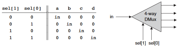
Inputs: in, sel[2]
Outputs: a, b, c, d
Function:
If sel=00 then {a=in, b=c=d=0}
else if sel=01 then {b=in, a=c=d=0}
else if sel=10 then {c=in, a=b=d=0}
else if sel=11 then {d=in, a=b=c=0}.
SPOILERS
One POSSIBLE implementation uses: DMux
| in | sel | a | b | c | d |
|---|---|---|---|---|---|
| 0 | 00 | 0 | 0 | 0 | 0 |
| 0 | 01 | 0 | 0 | 0 | 0 |
| 0 | 10 | 0 | 0 | 0 | 0 |
| 0 | 11 | 0 | 0 | 0 | 0 |
| 1 | 00 | 1 | 0 | 0 | 0 |
| 1 | 01 | 0 | 1 | 0 | 0 |
| 1 | 10 | 0 | 0 | 1 | 0 |
| 1 | 11 | 0 | 0 | 0 | 1 |
Inputs: in, sel[3]
Outputs: a, b, c, d, e, f, g, h
Function:
If sel=000 then {a=in, b=c=d=e=f=g=h=0}
else if sel=001 then {b=in, a=c=d=e=f=g=h=0}
else if sel=010 ...
...
else if sel=111 then {h=in, a=b=c=d=e=f=g=0}.
SPOILERS
One POSSIBLE implementation uses: DMux, DMux4Way
| in | sel | a | b | c | d | e | f | g | h |
|---|---|---|---|---|---|---|---|---|---|
| 0 | 000 | 0 | 0 | 0 | 0 | 0 | 0 | 0 | 0 |
| 0 | 001 | 0 | 0 | 0 | 0 | 0 | 0 | 0 | 0 |
| 0 | 010 | 0 | 0 | 0 | 0 | 0 | 0 | 0 | 0 |
| 0 | 011 | 0 | 0 | 0 | 0 | 0 | 0 | 0 | 0 |
| 0 | 100 | 0 | 0 | 0 | 0 | 0 | 0 | 0 | 0 |
| 0 | 101 | 0 | 0 | 0 | 0 | 0 | 0 | 0 | 0 |
| 0 | 110 | 0 | 0 | 0 | 0 | 0 | 0 | 0 | 0 |
| 0 | 111 | 0 | 0 | 0 | 0 | 0 | 0 | 0 | 0 |
| 1 | 000 | 1 | 0 | 0 | 0 | 0 | 0 | 0 | 0 |
| 1 | 001 | 0 | 1 | 0 | 0 | 0 | 0 | 0 | 0 |
| 1 | 010 | 0 | 0 | 1 | 0 | 0 | 0 | 0 | 0 |
| 1 | 011 | 0 | 0 | 0 | 1 | 0 | 0 | 0 | 0 |
| 1 | 100 | 0 | 0 | 0 | 0 | 1 | 0 | 0 | 0 |
| 1 | 101 | 0 | 0 | 0 | 0 | 0 | 1 | 0 | 0 |
| 1 | 110 | 0 | 0 | 0 | 0 | 0 | 0 | 1 | 0 |
| 1 | 111 | 0 | 0 | 0 | 0 | 0 | 0 | 0 | 1 |
#1.3 Implementation
Similar to the role of axioms in mathematics, primitive gates provide a set of elementary building blocks from which everything else can be built. Operationally, primitive gates have an “off-the-shelf” implementation that is supplied externally. Thus, they can be used in the construction of other gates and chips without worrying about their internal design. In the computer architecture that we are now beginning to build, we have chosen to base all the hardware on one primitive gate only: Nand.
We now turn to outlining the first stage of this bottom-up hardware construction project, one gate at a time. Our implementation guidelines are intentionally partial, since we want you to discover the actual gate architectures yourself. We reiterate that each gate can be implemented in more than one way; the simpler the implementation, the better.
- Not: The implementation of a unary Not gate from a binary Nand gate is simple. Tip: Think positive.
- And: Once again, the gate implementation is simple. Tip: Think negative.
- Or/Xor: These functions can be defined in terms of some of the Boolean functions implemented previously, using some simple Boolean manipulations. Thus, the respective gates can be built using previously built gates.
- Multiplexor/Demultiplexor: Likewise, these gates can be built using previously built gates.
- Multi-Bit Not/And/Or Gates: Since we already know how to implement the elementary versions of these gates, the implementation of their n-ary versions is simply a matter of constructing arrays of n elementary gates, having each gate operate separately on its bit inputs. This implementation task is rather boring, but it will carry its weight when these multi-bit gates are used in more complex chips, as described in subsequent chapters.
- Multi-Bit Multiplexor: The implementation of an n-ary multiplexor is simply a matter of feeding the same selection bit to every one of n binary multiplexors. Again, a boring task resulting in a very useful chip.
- Multi-Way Gates: Implementation tip: Think forks.